Why?
So after my Fairground light strip adventure a little while ago, I was sat looking at the lights under my shelf and wondered how different it might look if the Cabochons had legit lights inside it and not the tiny little 8mm led that was on the WS2182B LED strips that I ended up using.
I looked around to see if I could purchase a module similar to the modern LEDs they use in cabochons but with addressable LEDs, I did find one eventually, but it run from 24v, used some weird protocol and I'm pretty sure wasn't fully addressable.
So I set out to make my own little version of the modules that used WS2812C LEDs in a, hopefully, more original way than that single led mention previously.
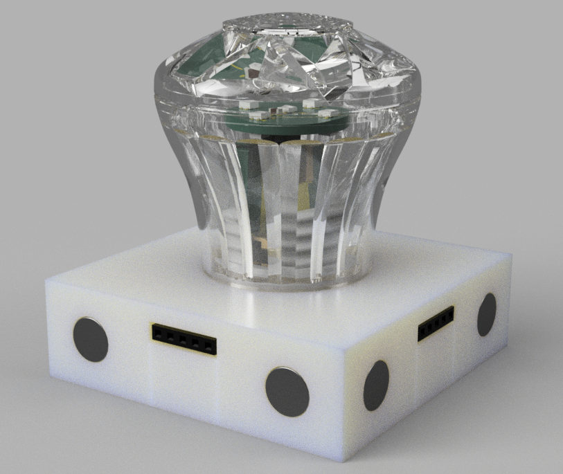
And then I just kept expanding the design, until I eventually came up with this abomination...
(I am kind of proud how the Cabochon turned out, it took way to long to model it)
LED Selection
It did take me a little while to work out what type of addressable LED to use, I was originally going to use WS812B-5050 LEDs but it turns out that they consume about 20Ma per channel per LED, so 60Ma per LED at full brightness set to White, Which doesn't sound like a lot, but it quickly adds up, especially when you have to use more than 1 LED per Cabochon.
So eventually I stumbled across the WS2812C which, according to the datasheet, uses 5Ma per channel, so 15MA per led, instead of 60Ma. Now obviously the brightness will be affected, but that doesn't really matter to me as they aren't going to be used to illuminate an entire room.
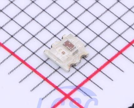
Above is the most common variant of the WS2812C I could find, which is the WS2812C-2020, but it was a little too small and didn't have the nice little plastic package surrounding the led.
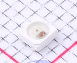
I did find the WS2812C-2427, The only place I could actually find it to purchase was LCSC, so I'm not sure if its some version that didn't catch on so they gave them to LCSC to flog for cheap or if they are new enough they haven't caught on yet. So I brought like 1200 of them😅 Don't blame me, they was cheap and shipping costs don't change much based on the quantity purchased, so it made economical sense... in some way.
PCB Design
I'm no stranger to designing PCBs so I figured I would make my own little module, obviously it wont be up to commercial standards, but it would be low voltage and not massively dangerous if something did go wrong.
The PCB isn't the biggest problem I had whilst designing this, but trying to work out the best way to securely attach the LED PCB to the extender PCB took far to long. It was a choice of using male / female headers everywhere, which is expensive and less secure or soldering them with some weird tab system I had seen on some cheap products throughout the years.
In the end I went for a mix of the two, The main LED board has some header pins on it, which are soldered to an extender board to raise the LEDs up inside the Cabochon, That extender board has a male pin header to connect to the female connector on the main "Node" PCB within the Node case.
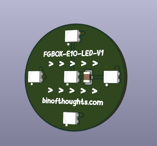
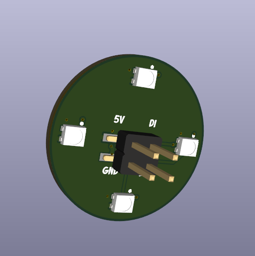
The front of the FGBOX-E10-LED PCB has 5 LEDs and the back has 4 LEDs, I wasn't sure exactly how many LEDs I would need to light up the Cabochon evenly, but figured this is a good start. The LEDs are wired is such a way that all of the LEDs within the Cabochon are connected to the same Data Input, so will all be the same color without having to setup some weird segments within WLED, The data output from a single LED is then used as the data input for the next Cabochon, should you connect up any subsequent boxes.
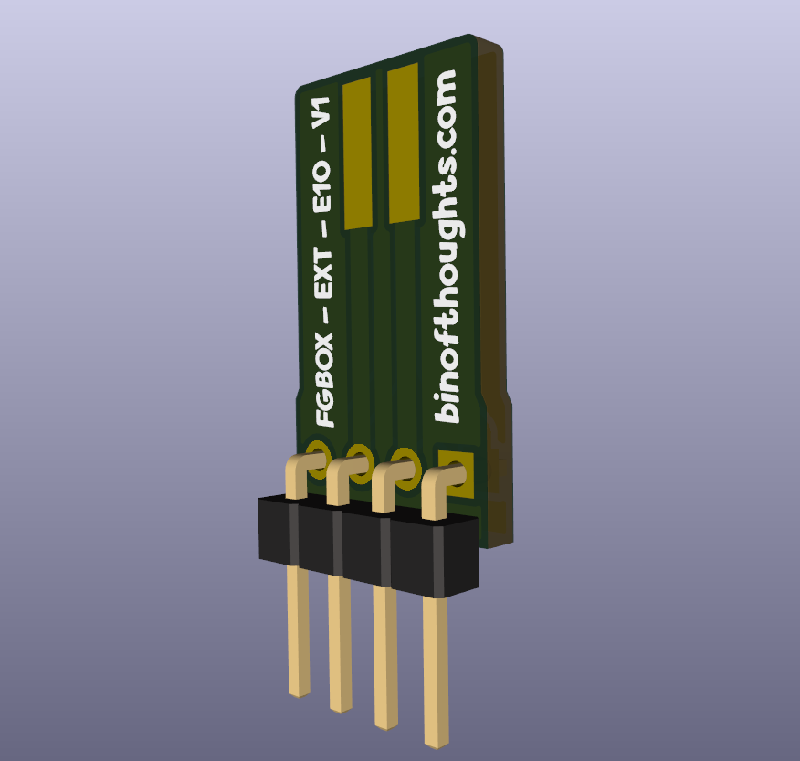
I originally intended for the smaller E10 and larger E14 Cabochons to use different LED boards as the size difference would presumably affect the spread of the light from the Cabochon, but I'm going to wait until I've tested the E10 version first and see if that would work in the E14 version, if it does then that would be nice.
The extender PCB and LEDs will plug into a Node / Controller PCB, I was hoping to design a board could be used for both controller and node but I had a self imposed deadline and couldn't be bothered to work it out. besides the node PCBs are slightly smaller so in theory cheaper to make.
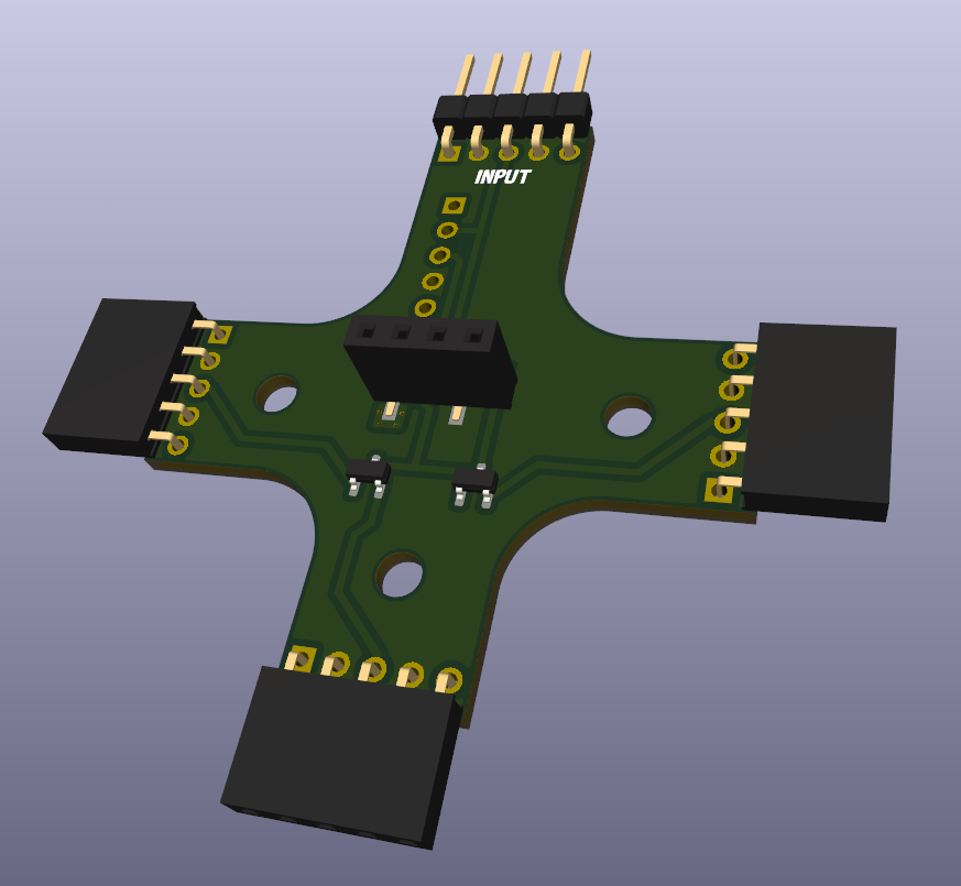
The node PCB has 1 input for data in, 3 outputs for data out, a vertical header for the LED board to connect to and some diodes to stop the any potential outputs that might be connected together from interfering with each other, although they are probably redundant.
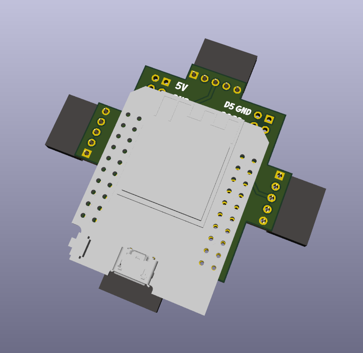
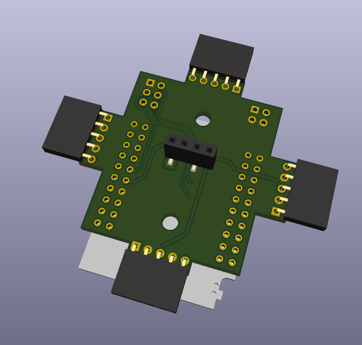
OK so I will admit, the design of the controller board leaves ALOT to be desired. I wanted to use an off the shelf ESP32 module because they are easier to replace should it die and they typically work out cheaper than fully incorporating the ESP32 chip into the design. Also I just wanted to do this relatively quickly.
The Gray thing in the first picture is the ESP32 D1 Mini, they are pretty cheap and should do the job just fine.
It has some other break out pins for potential expansion in regards to IO, but I haven't gone beyond that. It also includes a 4 pin header for 5V power input.
The controller board only features female headers as its an output only device. You can connect Nodes to the Controller but you cant connect 2 controllers physically together. At least not the Data lines.
If you have no intentions of using the ESP32 WIFI / Bluetooth features then you could probably get away with a Pi Pico and a few buttons for controlling brightness or something. If I get bored at some point and I like the final results of this experiment then ill consider designing a board that uses the Pi Pico.
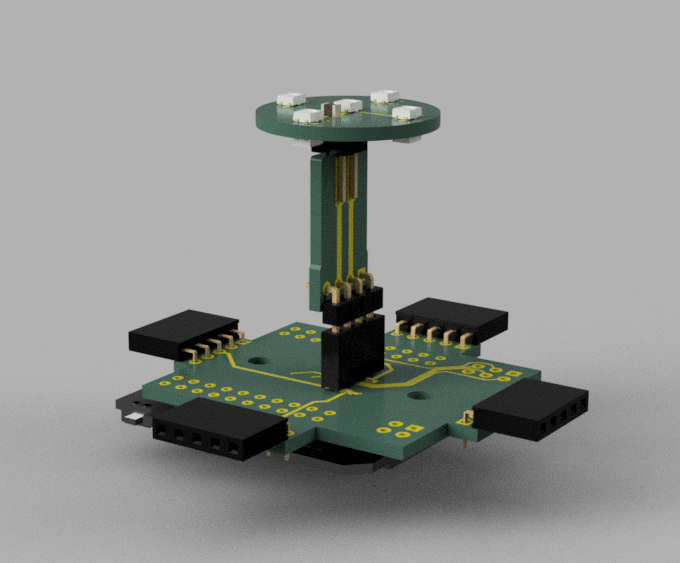
Above is a render of the controller box PCBs all constructed, Hopefully it works as intended 😅
The Case
The case was a bit of a bitch to work out. I had to figure out how to connect the boxes easily but securely, and also the best way to make the electrical connections between the boxes. I knew magnets was the way to go, but I couldn't work out if I wanted to try and use magnets as a way to do the electrical connections or just the mechanical connections. I looked around at some other ways of connecting things using magnets, like how magsafe works, but although the connectors are available, they are kind of expensive, like £1-2 expensive, which is a lot when you need at least 4 per box. So I looked at pogo pins and although they aren't expensive as such, the shear variety of them and uncertainty of how easy they will be to obtain a specific variant in the future, I decided against them and went with traditional pin headers / sockets.
The case fits both node and controller PCBs.
I chose 8mm magnets for mounting because I have some DC Barrel jacks from a previous project that uses an 8mm hole, so you can just drill out a magnet hole to use for power input.
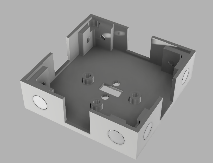
The design isn't perfect by any stretch of the imagination, but it prints easy. Obviously the design can be changed and improved upon over time or when the need arises.
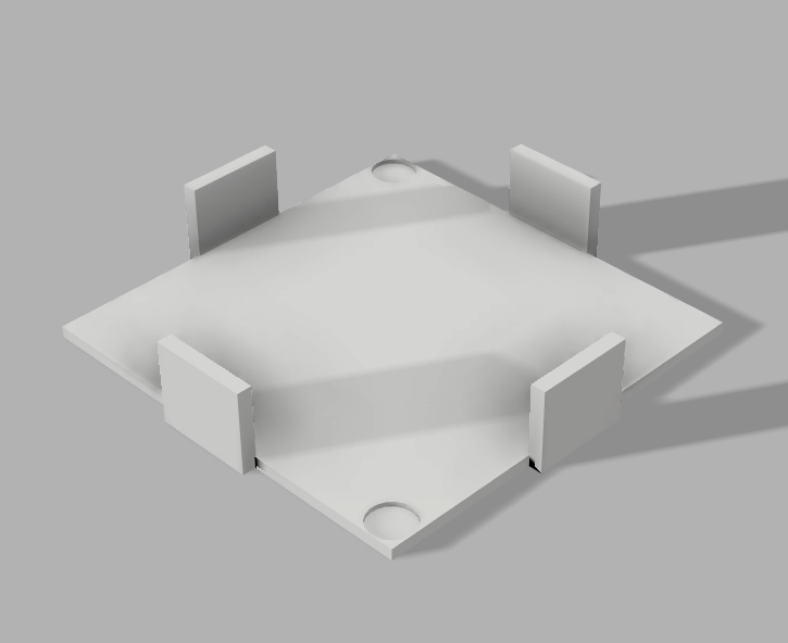
This is the cover / bottom for the base, I couldn't work out how to get the node / controller PCB into the case without soldering it in place, which I didn't want to do, so I ended up doing this weird cut out design so the PCBs can be slot into place and the bottom cover will cover the holes. It also has little cut out area for some 6mm x 2mm Neodymium magnets to keep the cover attached to the base.
Oh, those magnets aren't 2mm either, they are closer to 1.6mm.
The magnets on the outside of the box are 8mm x 3mm magnets, which again, isn't the size they state, instead these ones are 3.5mm thick, not 3mm 🤷♂️

Mounting the Cabochon
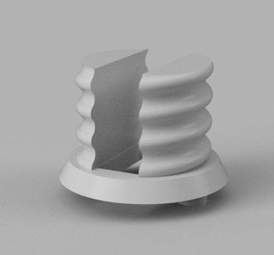
I had to work out what thread the Cabochons use for mounting, which turned out way easier for the E10 Cabochon as it just uses an E14 socket thread... I have no idea why. The Extender PCB is as small as I could get away with, but it did mean i had to slice out the top of the E10 mount, its still fairly solid and if you break it, it can be reprinted.
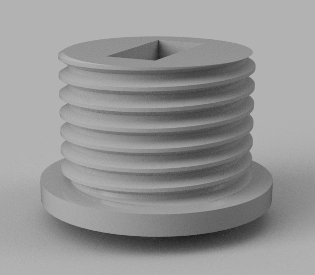
The E14 Cabochon though uses a thread I have no idea the name of. After a few prints trying to work out which thread would work, I had to modify Fusion360 thread data to create a custom thread, The best way to describe the thread is probably a bastardized M19 thread with 1.75mm pitch, but then scaled vertically by 5%. I'm not sure if the extra 5% needed was due to 3d printing dimensional issues or if it just works out at the correct thread type.
Each of the Mounts have cutouts for the Extender PCB to slot though and 2 little mounting nubs on the bottom to help align with the case, but they could probably be removed and make printing without supports possible if you just glue the mount to the base.
What Now?
I'm waiting for LCSC to deliver the parts and for JLCPCB to deliver the PCBS, When they arrive I'll make one up and see how it goes and make a new post about it, if it all works as intended then I will probably make the design files available.
Oh and this is the first time using KiCad, so I am expecting some errors on the PCBs somewhere. I usually use Eagle but I'm trying to move to more open software that doesn't want to take every penny you have every month just to use the software once every 3 months. I have yet to move away from Fusion360, Ive tried a few different CAD packages and i just cant be bothered to put in the effort to learn it, especially when useful documentation is either outdated or very few and far between. Switching from Eagle to KiCad has so far been surprisingly seamless, and I'm kind of preferring it so far.
